
Lidar Sensor Detection to Unity
Calculating Coordinates for Real Control Points in a Unity Project Using Lidar Sensors
When working on interacting with real-world control points using lidar sensors. Here’s a detailed guide on how to calculate the coordinates to achieve this:
- Determine the Width and Height of the Projection from the Actual Projector:
- For this example, we’ll use a width of 320cm and a height of 180cm (the actual width is 318.6cm).
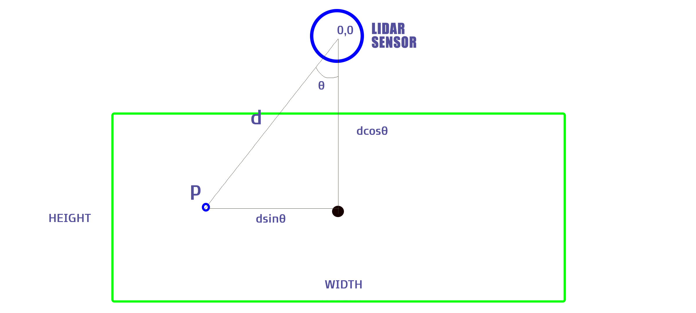
- Calculate the Height and Width Using Trigonometric Functions:
- The height is calculated using ( \cos(\theta) ).
- The width is calculated using ( \sin(\theta) ).
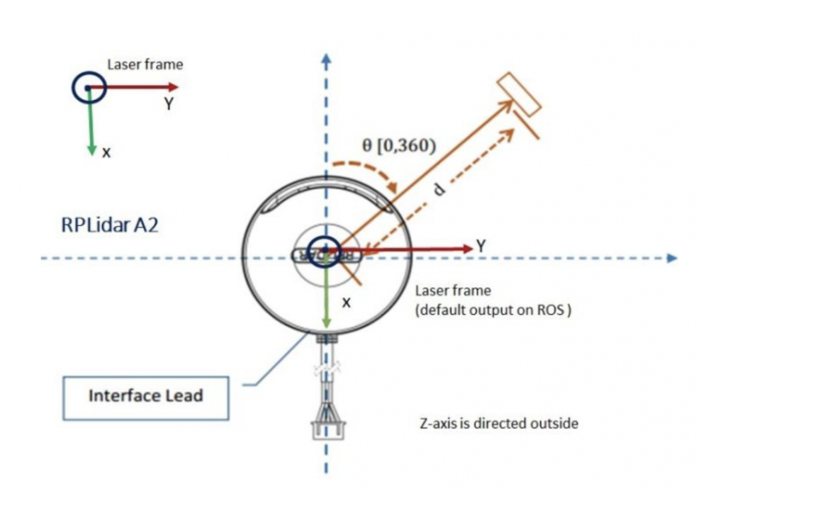
- Adjust the Angle Theta for Coordinate Compatibility:
- Add 180 degrees to ( \theta ) to make it compatible with the coordinate system.
- Since the direction of theta’s increase is opposite to typical mathematical conventions, we use ( 180 - \theta ) for calculations.
- refer to the manual image below.
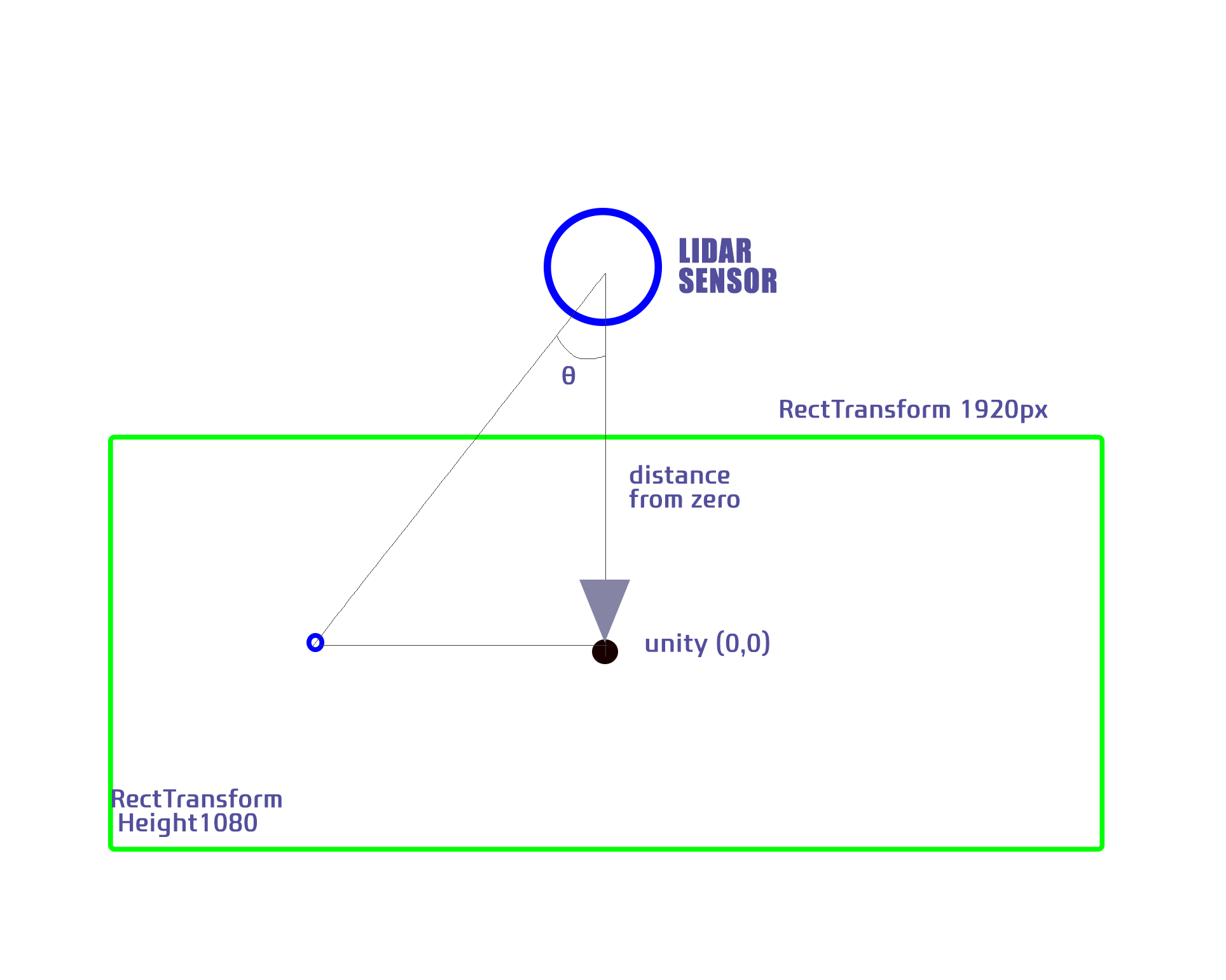
- Integrate with Unity:
- Assume a resolution of 1920x1080 Full HD in Unity.
- Calculate the Scaling Factor:
- Given the actual height is 1800mm and Unity’s height is 1920 units, calculate the scaling factor accordingly.
- Adjust Coordinates for Unity’s Origin:
- Since the origin (0,0) in Unity is the center, subtract the distance from the sensor to the center to calculate the coordinates. Note that only the y value is affected by this adjustment.
- Test and Adjust for Perspective:
- Conduct real-world testing to ensure proper functionality and adjust for perspective as needed.
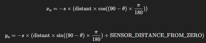
- Final Formula:
- After considering the scaling and the adjustments, the final formula for the coordinates in Unity is as follows:
[ x = -\text{screenRatio} \times (\text{distant} \times \cos((90 - \theta) \times \frac{\pi}{180})) ]
[ y = -\text{screenRatio} \times (\text{distant} \times \sin((90 - \theta) \times \frac{\pi}{180}) + \text{SENSOR_DISTANCE_FROM_ZERO}) ]
where:
- (\theta) is the angle from the lidar data.
- (\text{screenRatio}) is the ratio between Unity’s height and the actual height.
- (\text{distant}) is the distance measured by the lidar sensor.
- (\text{SENSOR_DISTANCE_FROM_ZERO}) is the fixed distance from the sensor to the center of the projection.
- Alternative Formula Using the Relationship Between Sin and Cos:
- You can also adjust the formula using the relationship between sin and cos for potential optimizations or specific cases.
Example Calculations
- Height and Width Calculations:
- Height: ( h = 180 \times \cos(\theta) )
- Width: ( w = 320 \times \sin(\theta) )
- Angle Adjustment:
- ( \theta’ = 180 - \theta )
- Scaling Factor:
- Actual height: 1800mm
- Unity height: 1920 units
- Scaling factor ( s = \frac{1920}{1800} )
- Coordinate Adjustment:
By following these steps, you can successfully map real-world control points to Unity coordinates, ensuring accurate interaction within your Unity project. This process involves understanding the trigonometric relationships, scaling factors, and proper adjustments for Unity’s coordinate system. Conducting real-world testing is crucial to fine-tune the setup and ensure everything works as expected.
These steps outline how to calculate and adjust coordinates for a Unity project using lidar sensor data, ensuring proper scaling and perspective adjustments for accurate interaction.